

Case Study; 25 minute read
Rheinmetall UK Additive Manufacturing Case Study
Cost Effective Metal AM for Low Volume Production and Deployable Support
By Julian Wright, Technology Programmes Manager, Rheinmettal UK.
Published: 2026-06-03
Disclaimer: This case study has been reproduced by Rapidia with the permission of Rheinmettal UK. All intellectual property, trademarks, and original research belong to Rheinmettal UK and the original author. It has been edited by Rapidia for formatting only. The content has not been edited or altered in any way. The views and opinions expressed herein are those of the original author and are shared for here educational and analytical purposes.
Background
Rheinmetall UK serves as a primary defence contractor in the UK and is delivering some of the British Army’s most important modernisation programmes, including Challenger 3 and Boxer. The business is investing in sovereign manufacturing capability across the UK including its latest investment in a new "UK Gun Hall" for barrel manufacturing. As production ramps up, advanced manufacturing technologies such as metal additive manufacturing have an increasingly important role to play in improving affordability, resilience and speed of delivery.
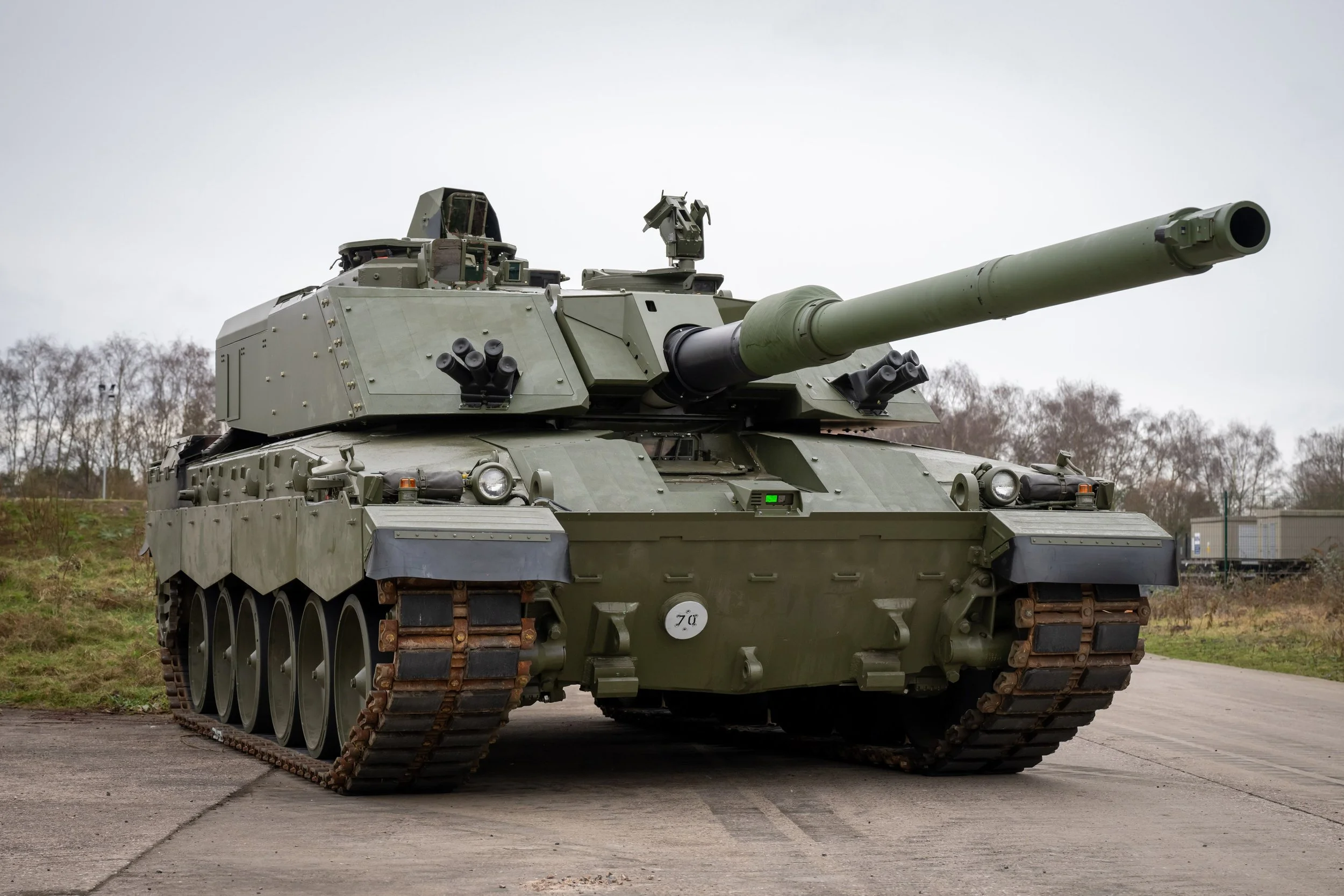
The new Challenger 3 Main Battle TankCan metal Additive Manufacturing be cost effective?
For over a decade now, the business has been exploring metal AM to manufacture vehicle parts. Our goal being to reduce production lead times and accelerate engineering development cycles. The primary focus has been on Laser Powder Bed Fusion (LPBF) as this has been the most mature technology. Over the years, we have demonstrated how we can design & manufacture parts for this process and even qualify safety critical parts for vehicles. Having demonstrated all of this, metal AM has still not made it into vehicle build standards.
The primary reason comes down to cost. The cost to manufacture metal AM parts with LPBF is substantially more than the current manufacturing methods, with the exception of castings. When required in low volume and where tooling costs can be mitigated, LPBF can be equivalent in cost to casting but with the benefit of being a much quicker supply route.
For military land vehicles the economics are often challenging. Parts tend to be bulky and hence require lots of material, don’t have significant complexity and also tend to be lower cost than, for example, aerospace components. Making a viable business case for change is therefore challenging. The typical mantra for AM, to consolidate parts, thereby reducing part count, mass and cost is challenging to realise. It requires fundamental change in the design approach, well trained individuals and programme opportunity. Furthermore, it also locks an organisation into the AM design since AM is the only method that can make these parts.
For broad adoption of metal AM within the industry, AM needs to offer a means to produce bulky, relevant parts with a piece part cost that is more competitive than the incumbent manufacturing methods.
Another key consideration is the financial viability of bringing AM technology in-house. The benefits of in-house capability can be significant. Not only does it provide greater production flexibly and speed, it also drives more cost effective designs due to the accelerated rate of learning within the engineering teams. For LPBF, in-house adoption seems unlikely due to the high capital expense, specific facilities and safety requirements. The current lack of designs for AM parts also means there isn’t sufficient throughput to warrant such an investment.
In the search for a metal AM technology that meets our needs, we analysed and tested a wide variety of alternate metal AM technologies, evaluating their application for low volume vehicle production and determine their financial viability.
-
Overview – LMJ is a process whereby metal feedstock is melted in a crucible. It is then ejected as a stream of small droplets of metal onto the build surface, progressively building up the shape of the desired part.
Pros - A cost competitive method of manufacture that has the potential to build parts quickly
Cons – Currently limited to Aluminium, equipment can have issues in reliably dispensing metal droplets over long prints. Inter layer fusion is problematic if the temperature differential between the droplet and the part is not kept constant. If only a heated build bed is used, as the part gets taller, the difference in temperature of the droplet and part becomes larger and larger until there is poor fusion between the droplet and part.
Assessment – Although the process is interesting, it is not mature enough to consider using.
-
Overview – A continuous welding process, be that by laser or arc. The feedstock is typically wire although powder can be used. The systems can be frame mounted or robot mounted to allow for complex shapes to be produced.
Pros – Using wire feedstock is very cost effective and DED systems can build up material quickly. A wide range of materials can be used allowing for process flexibility.
Cons – Equipment can command a high price, in excess of £1/4m. The thermal nature of the process means that temperature control within the part must be managed. There is a strong potential for part warping and internal stresses to build. It is debatable whether the typical, as printed, surface finish is suitable to be left visible in the end part. Parts require post machining once printed e.g. cutting from the build plate with a wire EDM, supports cut from the part and surfaces machined to tolerance. The cost of this post processing equipment and ongoing labour costs add up. The process is not very suitable to make small components with thin walls or internal features.
Assessment – When considering the cost of the equipment, the productivity of the machine and the cost of post processing to reach an acceptable surface finish, the business case for adoption of DED is currently challenging.
-
Overview – A method whereby a polymer filament doped with metal powder is used in a heated printer head to extrude beads of material layer by layer to build a part. The, as printed, parts are called green parts. These then need to be “de-bound”, which means to remove the polymer binder from the part. In this process, there is a significant proportion of polymer binder which must be removed by dissolving the polymer in a caustic bath. This creates what is known as a “brown part”. This then needs to be sintered in a furnace to get a solid metal.
Pros – the cost of equipment is lower than all other metal AM technologies. Consumer grade printers can be used to print the metal filament. Productivity can be enhanced by having more low-cost printers. There are a variety of furnaces available on the market to sinter the brown parts. Parts can be printed as “full density” or “partial density” meaning that a continuous outer skin can be maintained but with less infill material. This is useful for mass reduction without compromising the external form.
Cons – Parts need to be de-bound in caustic chemicals. This adds process time and uses hazardous chemicals. There is a limit to the section thickness that can realistically be de-bound, typically 10mm. Any thicker than this and it will take days to de-bind, slowing production. For example, parts need to be regularly weighed to see whether they have lost the required material before concluding the de-binding step. Parts can also be weakened and crack as a result. The metal filaments are quite costly impacting piece part affordability. In the sintering process, the high binder content can shorten the maintenance intervals for the furnace. There is also the potential for geometry to warp in sintering due to gravity acting on the metal when it is in its weakest state.
Assessment – The process limitations in maximum section thickness is a significant limitation for Rheinmetall UK’s use cases. The high material costs reduce the cost effectiveness of the process. The need for a chemical de-binding step adds time and therefore cost whilst also reducing process safety.
-
Overview – A sintered metal technique that uses polymer Selective Laser Sintering (SLS) machines to fuse a polymer coated metal powder feedstock. The SLS machine prints as normal and fuses the polymer together encapsulating the metal. After printing, the green part is then chemically de-bound to remove the polymer and then thermally sintered in a furnace to solidify the metal.
Pros – The cost of SLS machines has dropped significantly and this process enables existing machinery to be used for metal part production (subject to purchasing de-binding and sintering equipment or subcontracting the processes). A good selection of metal feedstocks are available since the polymer doesn’t interact with the metal.
Cons – Part wall thickness is limited due to the de-binding stage and part size is limited due to the mechanics of sintering. The time to de-bind can be lengthy. Parts with any sort of overhang will require supporting in sintering. This can either be done with modelling support structure into the original CAD and then cutting this away after sintering or printing a separate part setter and then hand assembling the setters and part on the sinter tray. The setter and part can be kept separate from one another by using a ceramic spray. Material porosity can be higher than processes like Direct Metal Laser Sintering (DMLS)
Assessment – As with FFF, the process limitations in maximum section thickness is a significant limitation for our use cases. Similarly, the need for chemical de-binding adds time and cost. The Additional labour times for assembling setters and parts would add to overall production costs and process variability.
-
Overview – Another sintered metal approach but this time a wax mould is 3D printed layer by layer. At the end of each layer, a metal paste is spread to fill the mould. The water in the paste is dried via a vacuum heating method so as not to melt the wax and then the process is repeated. Upon completion of printing, the wax is removed and the parts liberated. They then need to be thermally sintered to solidify the metal. The machines are designed as a carousel where each stage performs a specific function. Although this makes the machines larger, it greatly increases the productivity enabling multiple batches to be manufactured at the same time.
Pros – if parts can be tightly packed then the mold jet process can be very cost effective and highly productive. Feedstock prices are very competitive and can even be mixed on site. Used wax can be downcycled to reduce the impact of waste. Surface quality of parts should be exceptional with the process and there is an innovative in-process quality assurance function using image analysis and defect repair process which should add confidence to the quality of the final part.
Cons – The printer equipment is expensive, upwards of £300k for the smaller printer, over £1/2m for the larger (note a furnace is also required). It also requires a fair amount of factory floor space. The production time for each part is fairly slow taking about 6 minutes per layer. If the parts have an open form factor and cannot be nested then they can become more expensive to manufacture. As with Cold Metal Fusion, if parts have overhanging sections, a setter will be required in the furnace to avoid warping. These need to be printed separately and pieced together by hand before sintering.
Assessment – MoldJet technology is an interesting mass manufacture method for smaller components. It requires a significant upfront investment which makes adoption of the technology more challenging unless throughput can be achieved on day 1.
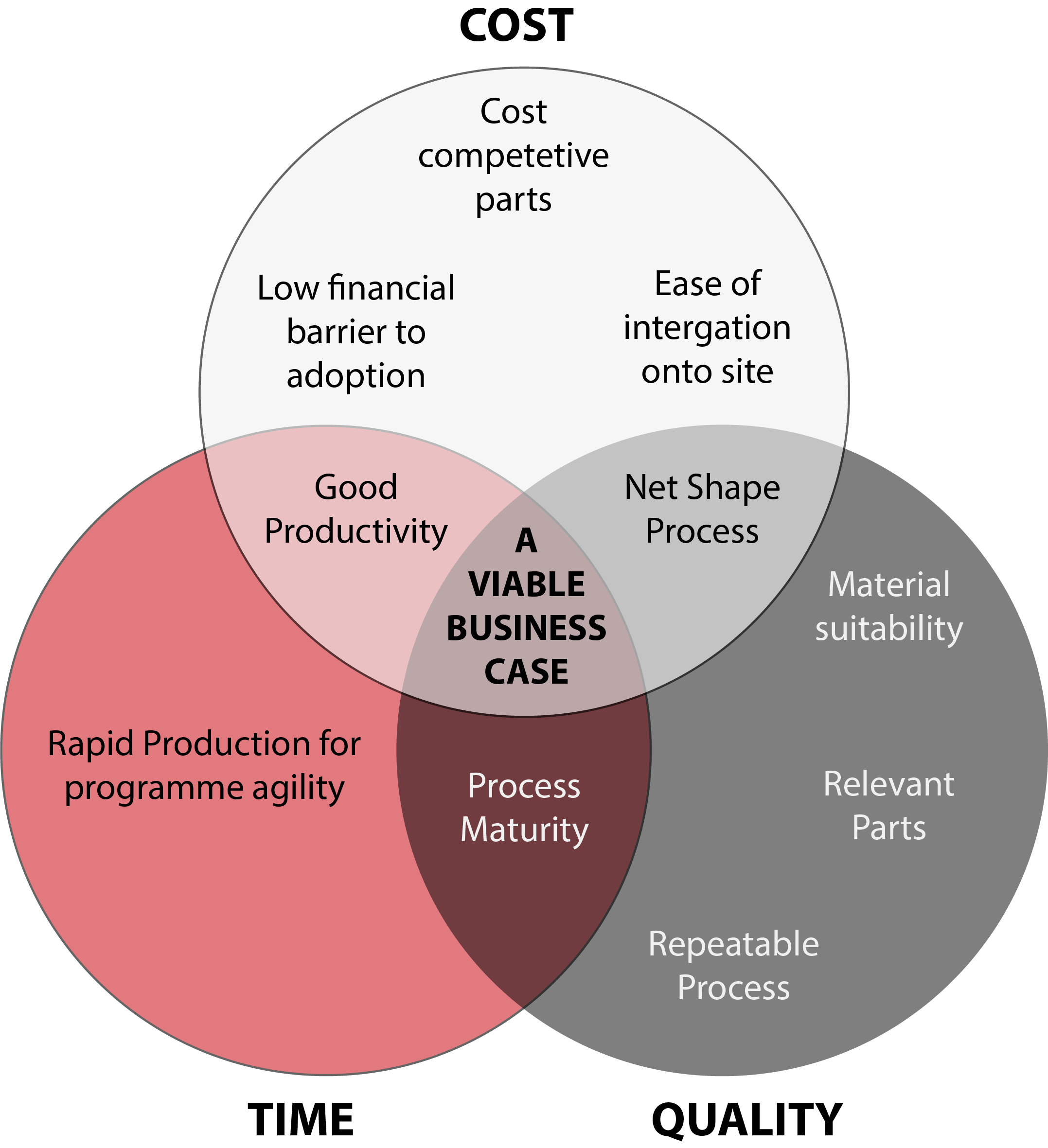
Requirements for in-house adoption of Metal AMFrom this search, we realised that we needed a technology which could balance cost, time and production quality. The process had to be able to manufacture relevant parts for the business with a viable business case. A low financial barrier to entry is also a crucial factor to aid in adoption since this would make it easier to demonstrate a return on investment.
The discovery of Metal Paste Deposition Additive Manufacturing (MPD)
Mid-way through 2025, we discovered an intriguing YouTube video showing a novel method of metal part production that we hadn’t seen before, a cast to sinter method. It was presented by a gentleman, unknown to us at that time, called Dan Gelbart who explained in detail how to turn metal powder into solid metal forms with high precision.
His video drove our curiosity leading us to discover a small technology company in Vancouver Canada called Rapidia Tech Inc. Established in 2016, they offer an AM technique which they claim is:
“The simplest, fastest and most affordable way to metal 3D printing complex and strong parts in only two steps”.
Their AM process, Metal Paste Deposition (MDP), seemed to offer a capability which could produce relevant parts with minimal machinery and labour. Everything that’s needed for low-cost part manufacture. Unlike the Cast to Sinter method that Dan presented, the MPD approach enables support structures to be build at the same time as the part, allowing complex structures to be printed with minimal labour input.
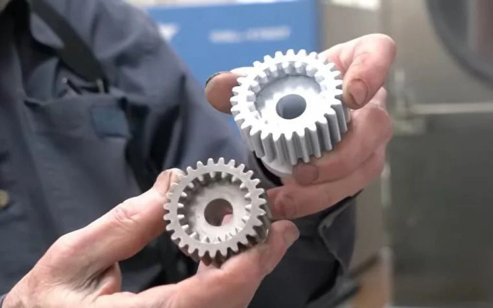
Rapidia’s Cast to Sinter manufacture method, SLA master part and cast metal paste partHow does Metal Paste Deposition work?
MPD is similar in many ways to metal FFF except instead of using a filament with a high ratio of polymer binder to metal powder, MPD uses a viscous metal paste made with metal powder, approximately 10% by weight of water and a very small fraction of binder. The paste composition is key to the process advantages.
In the process, the paste is pushed into the print head under pressure whereby it is precisely deposited onto the build plate. No heat is used to extrude the metal. At the end of each layer, a halogen lamp is used to evaporate the water content leaving just the metal paste and the binder. The use of water as the carrier benefits the process through the water tension in the droplets. The water tension ensures that there is a uniform structure to the paste which remains once the water is evaporated. The remaining “green part” then consists of a highly dense matrix which can then be thermally de-bound and sintered in a single process.
The printers provide the means to print two pastes in a single print. This typically is a metal paste and a ceramic paste. The ceramic paste is used as both a support material and release agent within the process. As with many AM techniques, angles greater than 45 degrees need supporting. The designer can choose to either support these with ceramic or metal paste. Ceramic supports have the benefit of powderising in the sintering process meaning that they can be simply brushed away after sintering. They don’t however provide any mechanical support within the sintering process. Therefore, heavy sections of parts which would otherwise sag under gravity need a different kind of support solution. The answer is to use metal supports. Metal supports are printed at the same time as the part and, like the ceramic supports, are automatically generated by the slicing software. The software also automatically places ceramic material between the support and the part meaning that they can be removed by hand after the sintering process. Being able to remove supports by hand saves a significant amount of time and expense which is one of the main contributions to the affordability of the process.
In MPD, parts are often printed on a shrinkage raft. This enables the sintered part to consolidate in the furnace and see minimal stresses as it does so. The shrinkage raft is printed in the same material as the part and is separated by a couple of layers of ceramic paste. This enables the shrinkage raft to separate from the part post sintering without any machining.
The ”green part” has a consistency of chalk and can be easily worked prior to the sintering step e.g. can be sanded or marked. In this state it is quick and easy to remove material. The parts are then placed in the vacuum furnace, a sinter profile is selected and all the operator needs to do, is press go. A rapid cycle takes 12 hours in total, 8 hours of heating and 4 hours of cooling. After this, parts can be removed and used straight away or have some post processing steps undertaken as necessary e.g. painting, tapping, welding etc.
Currently Rapidia offer three materials, (others are in Beta testing) 316L Stainless Steel, 17-4PH Stainless Steel and Inconel 625. For Rheinmetall UK applications, 17-4PH is particularly interesting since it has significantly higher mechanical properties than many of the common grades of steel we specify. With the printing process being net shape, there’s usually no machining required so it’s okay using a harder steel. As a result, we can use 17-4PH stainless steel as a substitute, making use of the extra strength to offset any concerns of variability in the printing process.
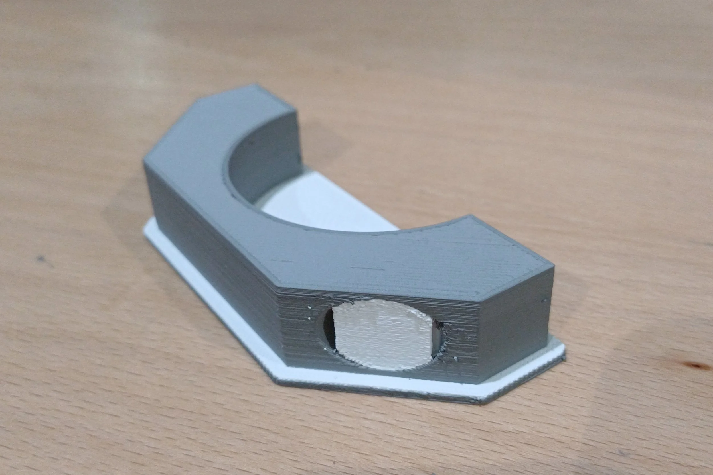
Example green part showing ceramic support and shrinkage raft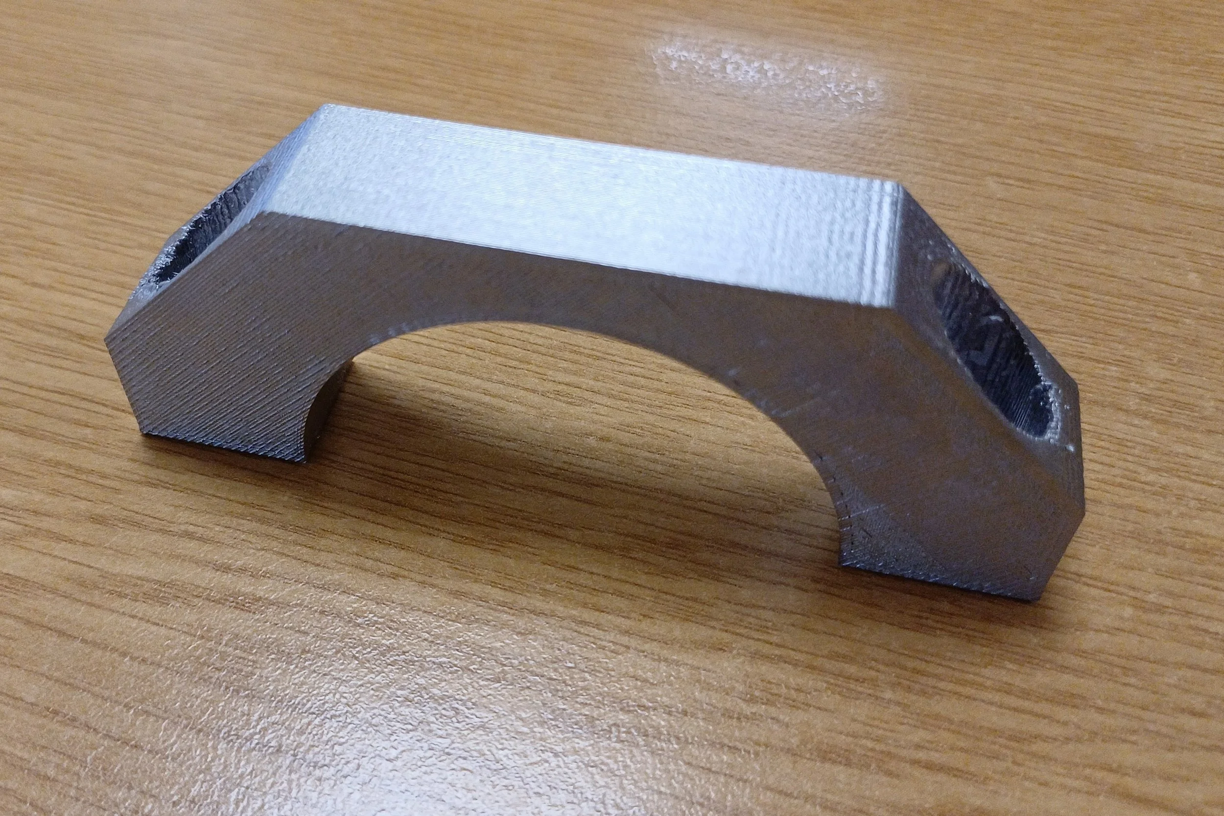
Same part post sintering, no post processing required (Challenger 3 bracket)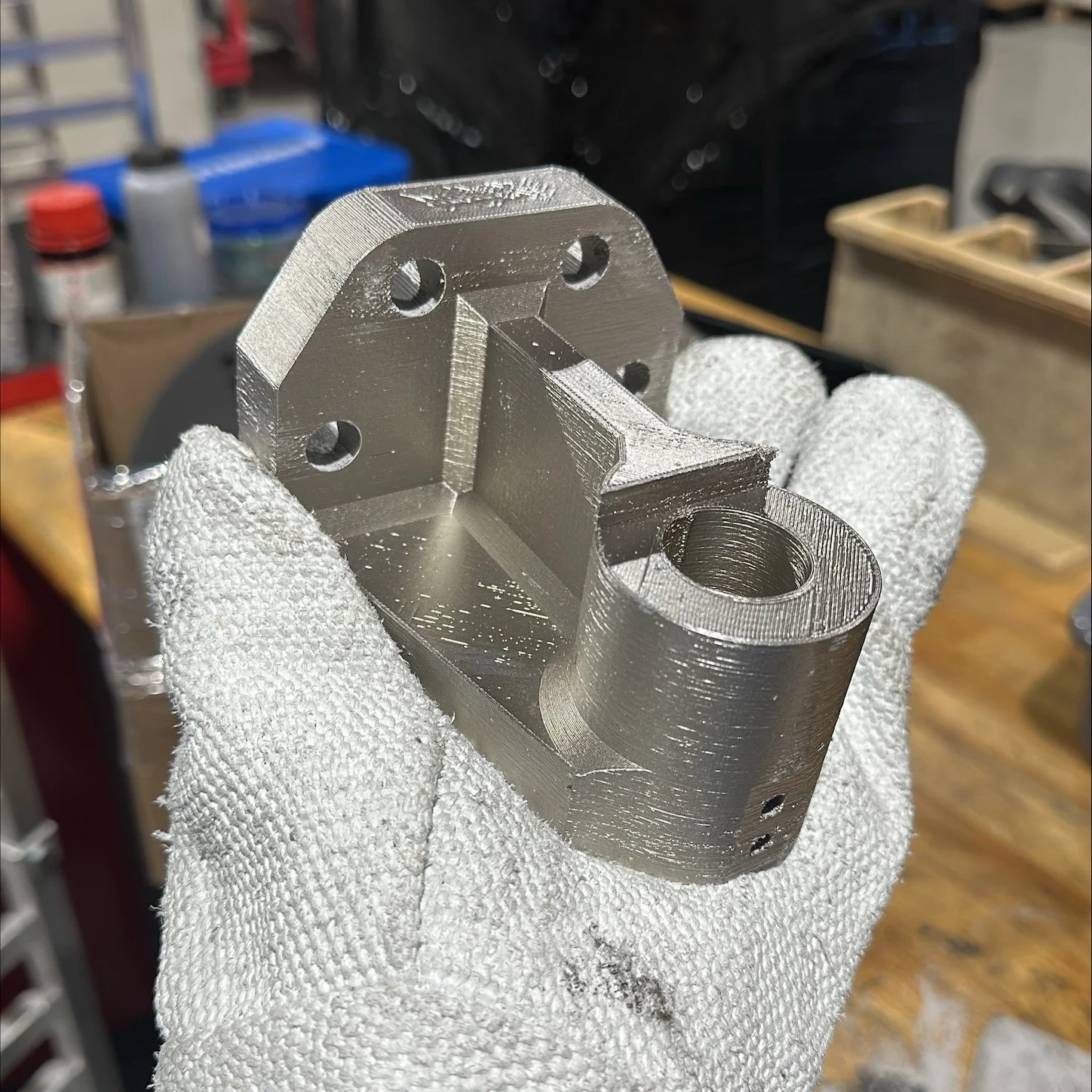
2.5kg sample part with 20mm thick wall sections demonstrated by RapidiaWhat’s the catch?
Rapidia had made some bold claims that had to be tested! What could the technology really do? Where are the limitations and could it meet our requirements for metal AM?
The area of greatest concern was material quality, and particularly whether this could be maintained in sections thicker than 10mm. Rapidia claimed they could produce quality metal in 50mm+ sections. Previous experience with sintered approaches had demonstrated that thick sections were a problem to produce. After a few calls with the team, we sent them a challenge. Two example parts to test the viability of thicker section parts.
The first was a 2.5kg part with maximum wall thickness of 20mm. The second, a smaller part of 706g had a maximum section thickness of 30mm. If Rapidia could demonstrate producing high density metal for these forms and section thicknesses then it would suggest that the process could have applicability to a wider range of Rheinmetall UK parts.
When we examined the parts, optical, SEM and CT X-ray, we found two porosity modalities in the material. Evenly distributed 1-4 micron spherical gas bubbles and larger 100-200 micron pores generated from the printing process. The small pores are an artifact of sintering. The larger pores are created through a few mechanisms in printing.
Toolpath generation in the slicing software – in the image below you can see how small gaps will be left where the infill pattern meets the 3 exterior walls at a 45 degree angle.
Accurate bead placement and flow calibration – if the material deposition is not well calibrated then there can be insufficient paste laid down leading to gaps between toolpath rows. This can lead to macropores being left in the finished metal.
In the sections we analysed, we could see that it is possible to get consistent dense structures throughout thick sections of steel. We observed occasional macropores however, on balance, the quality of steel is sufficiently good to warrant continued investigation.
By tensile testing printed ASTM E8 coupons, we examined the performance of the principle metal of interest, 17-4PH. For yield, the x/y print results were the same as Rapidia’s datasheet with the coupons printed in the z orientation giving a 30% better performance than in the official datasheet. Our results for UTS in x/y orientation however were 10% lower than the datasheet which may have been due to surface imperfections since we tested in the as printed state.
In summary, although the material isn’t isotropic, we found that there isn’t too much variability between prints. The performance of the material would significantly outperform many of the commonly specified steels we use such as S255 or S355.
As with all AM technologies, the process provides quite a lot of design freedoms. Additional features / complexity often come without any time or cost penalty. Conversely there are limitations as well. For example, printing and sintering tall aspect ratio parts is not easy. Sintering straight vertical walls will invariably lead to some deformation. Thickening walls out and providing additional support can resolve the issue. If a precise fit is required then it may be necessary to print additional material and plan to machine to tolerance after sintering.
Unique to this class of technology is the ability to print parts with partial infill and still retain a solid skin. It’s possible to print a stainless-steel part which exhibits an overall density similar to an aluminium part e.g. 25% infill. In the following example, two parts are printed but with different slicing parameters. The one on the left has a partial infill and the one on the right has full infill. The lattice structures to the left and right of each part is metal support being built to hold overhanging geometry.
We’ve found part tolerances can be good. For parts around 100mm in size, we observe a few tenths of a millimetre accuracy. Horizontal holes and vertical holes tend to print a little smaller than the CAD by a few tenths of a millimetre, which is useful for tapping without having to drill or ream beforehand. Horizontal hole accuracy in the z plane can be a little less due to movement in sintering e.g. 0.5mm. For good fit, reaming or drilling is recommended.
Printing isn’t the quickest at 35-40cc/hr (using a 0.4mm nozzle) however the overall production time is quick due to the small number of process steps. Most parts only require a rapid sinter cycle which is 8 hours of heating and 4 hours of cooling. This enables parts to be sintered overnight ready to fit in the morning. Many parts need no additional post processing afterwards. The stainless-steel parts only need painting for cosmetic purposes so going without saves manufacturing time and money. Printing with a 0.6mm nozzle can be somewhat faster due to the wider line width and higher layer thickness.
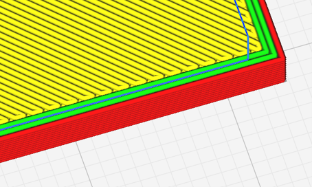
Toolpath generation in Cura slicer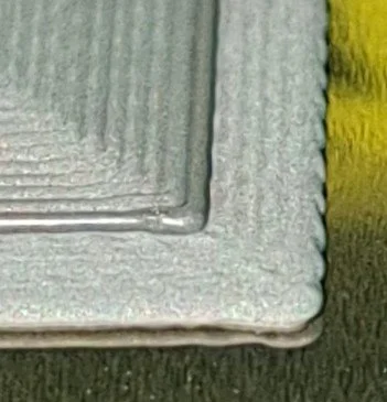
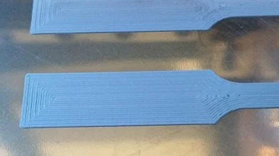
Magnification of material placement – beads are 0.4mm wideASTM E8 tensile test coupons being printed – concentric slicing pattern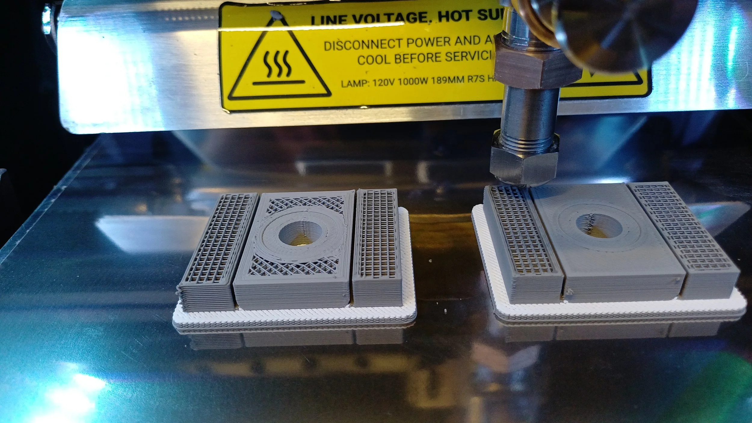
Two parts in print, left) partial infill, right) full infill.The decision to invest
With the investigation demonstrating that usable parts could be manufactured with an acceptable quality, the key area to examine was cost. Does the process enable lower cost parts and can it return on the investment.
This is what originally attracted us to the technology, the affordability. With most other metal AM technologies, making a viable business case to repay the initial capital is quite challenging and requires either high value parts or significant throughput. With MPD, the economics are much easier (Illustrative costs from Rapidia’s website):
Capital Cost – for the complete Conflux 1 system, the list price is £113k. This includes the furnace and a printer. Additional conflux 1 printers are listed at £13.4k each. A furnace can support four to five printers and so additional manufacturing capacity can be added with minimal additional capital. No other expensive production equipment is required to make parts. Post processing can be achieved with hand tools.
Installation costs – We needed to extend the 3-phase connection across the factory floor which cost a couple of thousand pounds. We also needed to spend a few hundred pounds on a gas bottle bracket. There was no other expenditure necessary.
Feedstock – The list price for stainless steel paste is $400 a cylinder with each cylinder holding 1000cc of paste. This is currently air freighted from the manufacturer and so costs about £0.41/cc delivered to the UK. Accounting for about 10% waste of material swapping cylinders over and other losses, a good guideline is £0.46/cc of usable paste. The ceramic paste was included with the support contract. In practice, very little ceramic support material is needed since larger supports tend to be specified in metal. We use about a 16:1 ratio of metal to ceramic support.
Operating Costs – The printer uses very little power. The print head rotor and stator need changing occasionally due to wear. Paste feed tubes need replacing if the paste is allowed to dry e.g. being left unused for several weeks or when changing the material. The nozzles, spring steel build bed and belts are all low wear items. The furnace will do 27 rapid sinter cycles on one high purity, 10.55m3 argon cylinder. Electricity consumption is about 62kW for a rapid cycle. For gas and electricity this can cost <£25 a sinter cycle. Apart from activated carbon to be replaced once or twice a year, there are no other consumables for sintering. The cost efficiency of the furnace will really add up over the years making it a good investment.
Labour Costs – it’s worth mentioning the impact the process has on labour costs compared to other AM processes. There’s no material preparation required, it comes pre-prepared from the manufacturer. No de-powdering is necessary and there is no part setting for the furnace. Once sintered, the supports can be removed by hand requiring no machining. Depending upon the application, the surface finish is often sufficient to leave unprocessed. The reduction in labour time required has a significant impact on piece part cost.
When considering all these cost benefits, we soon discovered that for small fabricated or machined components, typically where we print 100cc or less per part, the cost of manufacture with MPD can be cheaper than procuring parts in the supply chain, even at quantities of 100 - 200 parts.
Another, often overlooked, advantage is “just in time” production. With traditional procurement, small production runs often require that all parts are procured at once. These would have to be paid for upfront, stored and then drawn down over the course of the programme. With AM, parts can be made as required meaning that the company gets to maintain a healthier cash flow. This cash flow saving can pay for the equipment several times over. Furthermore, storing components for long periods increases the chance of damage or losses, requiring replacements. With AM, this is not an issue, any damaged parts can be easily replaced when needed. Just in time manufacture limits the potential for misplaced parts.
With the capital costs being so low compared to other metal AM technologies, it was far lower risk bringing the technology in-house. Having the printer and furnace in house greatly accelerates the rate of learning and design development. New ideas can be rapidly tested, and parts can be effectively cost optimised. The Challenger 3 washer injector housing is a good illustration of this. The original design was to be machined out of a solid block of brass. With Design for AM (DfAM) principles, the material used could be substantially reduced from 263g (25.3cc) of brass to 31g of Stainless Steel (8.5cc including raft), a massive 88% mass saving. Printing time was therefore reduced from about 4 hours to 1.5 hour per part enabling far higher productivity.
Due to the company’s unfamiliarity of this class of technology. The approach was to start by producing low criticality ancillary parts. This way we could demonstrate the potential of the technology with fewer engineering and production hurdles to overcome. With a handful of part types per vehicle across the 148 Challenger 3 vehicle production run, we found that we could easily make a positive return on investment whilst improving business agility. These parts would only take a small fraction of the capacity of the machine enabling further use and greater savings.
What couldn’t we cost in? The soft programme benefits are hard to put a value to. Being able to iterate part design quickly and test parts on the vehicle without having to wait 2 months for the supply chain to deliver a first article has a significant value to programme agility. Rework carries a lower risk since there are no procurement delays and the cost of change is much lower.
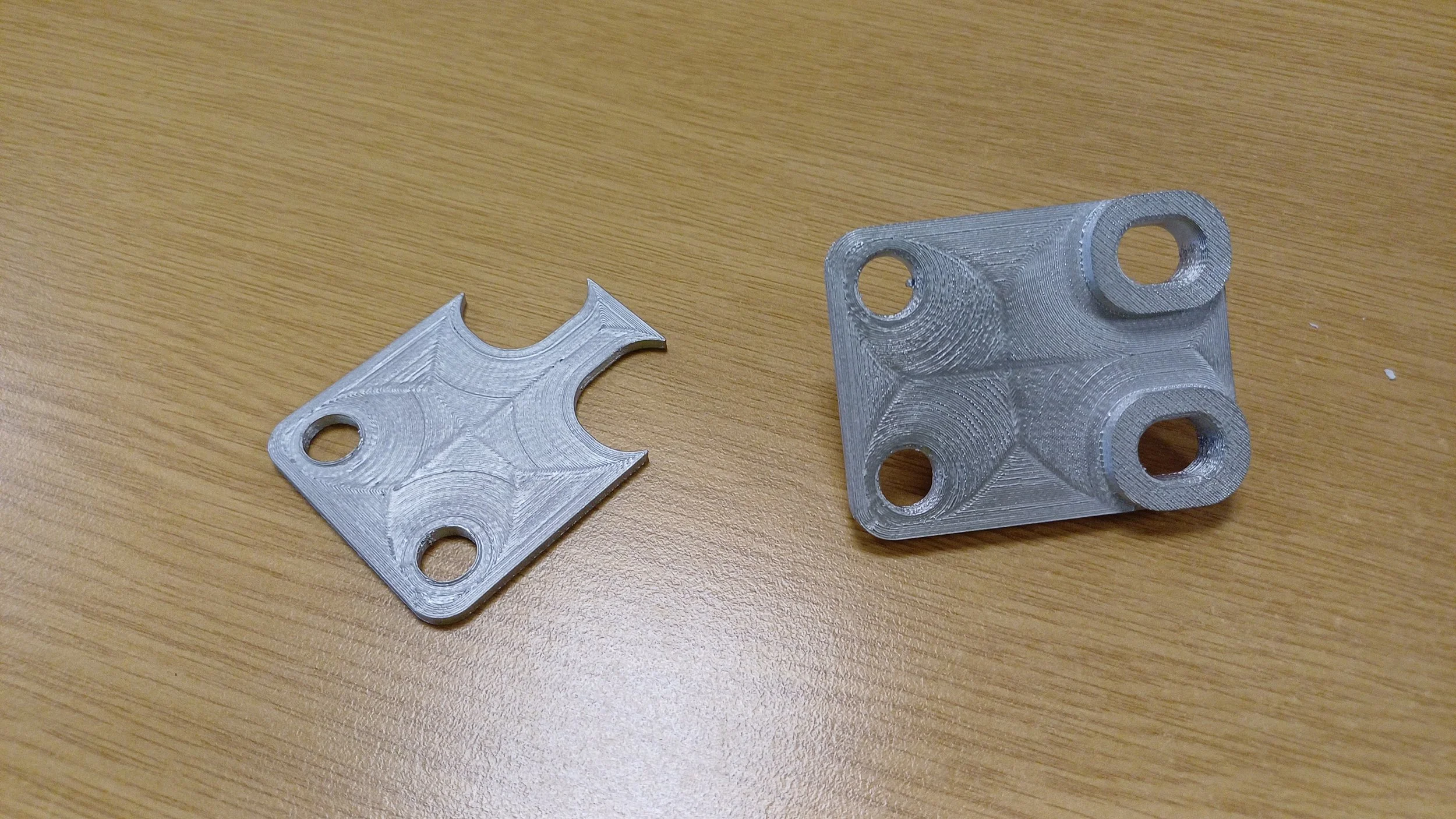
Challenger 3 production prototype with a non-flat base. Left) metal support, removed by hand, Right) underside of the part after removing the support, no post processing has been done. A concentric infill pattern has been used with this print.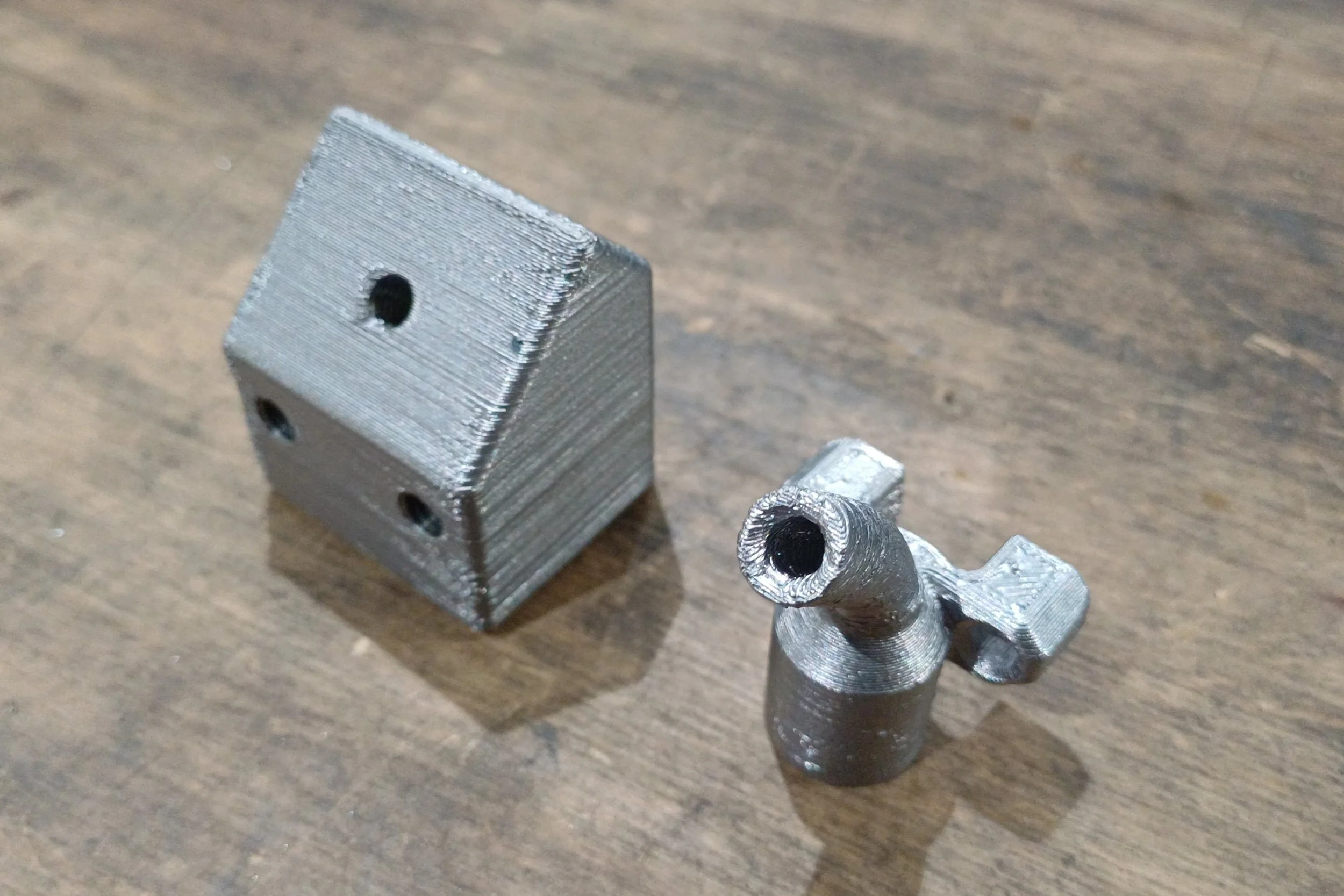
Original unoptimized design for a Challenger 3 washer injector housing next to an optimised design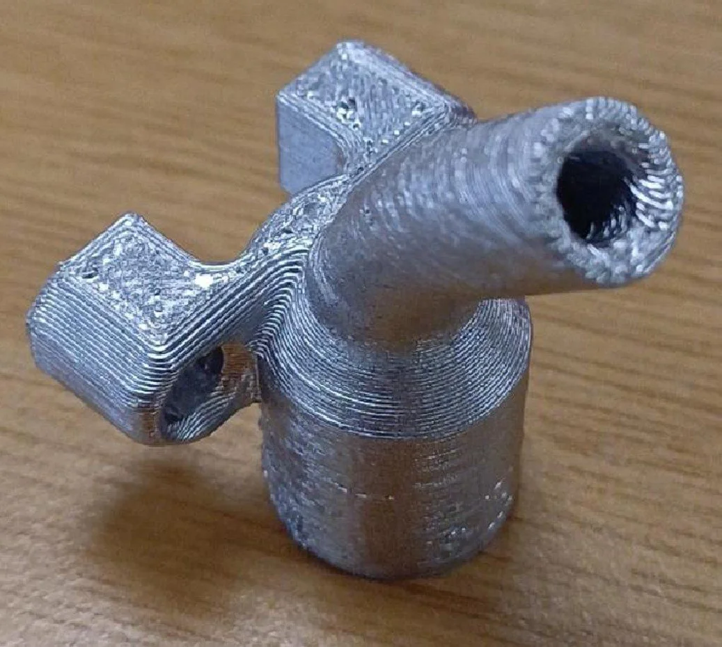
Closeup of the optimised design c.40mm high. Note, these are both as printed and require tapping before final use.
Installing the equipment on site
Late November 2025 two crates arrived at the factory. One with the conflux 1 furnace, the other with the conflux 1 printer. Unpacking was straightforward. The machines were lifted from their pallets to the factory floor with a forklift. Both machines have heavy duty casters enabling them to be moved by hand into their final positions.
Prior to their arrival we had ensured that the machines had a suitable location to be installed. For the printer, this was just ensuring sufficient space in a room with heating/air conditioning and access to 240v single phase power. For the furnace, it just needed a bit of space on the workshop floor and 3-phase supply. By specifying the oxidiser unit for the furnace, there was no need to install an exhaust and cut any holes in the building to the outside. The exhaust gas can be safely recirculated in the building. Next to the furnace, we installed a gas cylinder bracket for safely fixing an argon cylinder to the building.
Shortly after the equipment delivery an installer from Rapidia arrived. The installation and training for staff was delivered over 2 days. The first day was installation and test. For the printer, this was a matter of releasing the print gantry, assembling the print heads, connecting the paste lines, filling the water tank and plugging it in.
The furnace was just as easy. Plug it in, connect the argon gas, install the heating elements and make up the furnace furniture. It was set up and ready to go in a few hours. A USB stick can be used to download all the diagnostic and usage data as well as updating and adding sinter profiles.
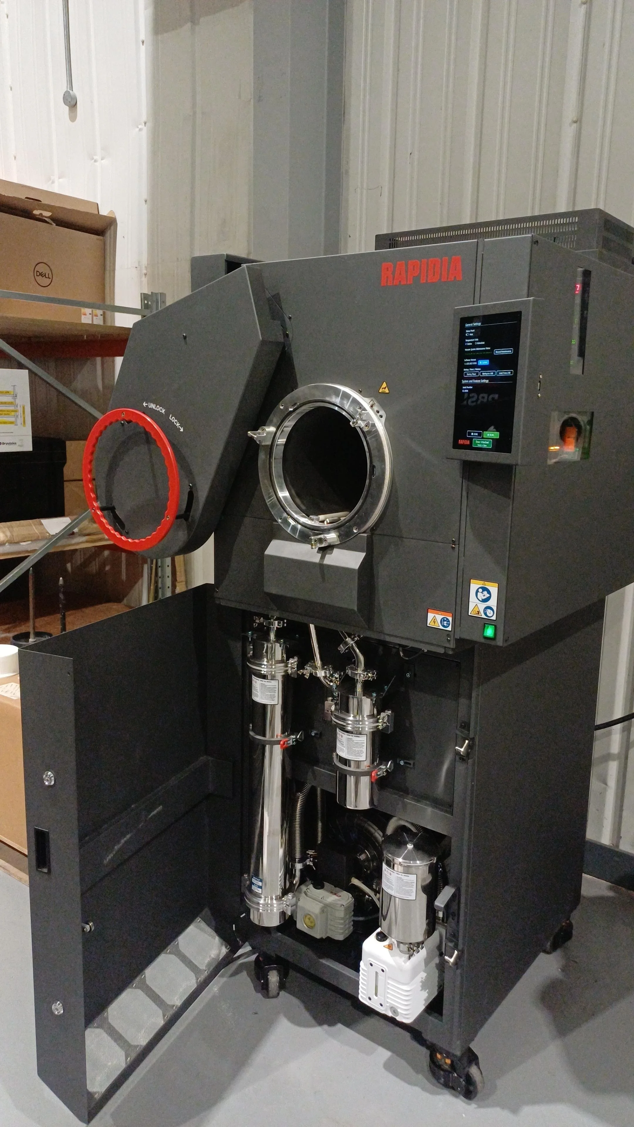
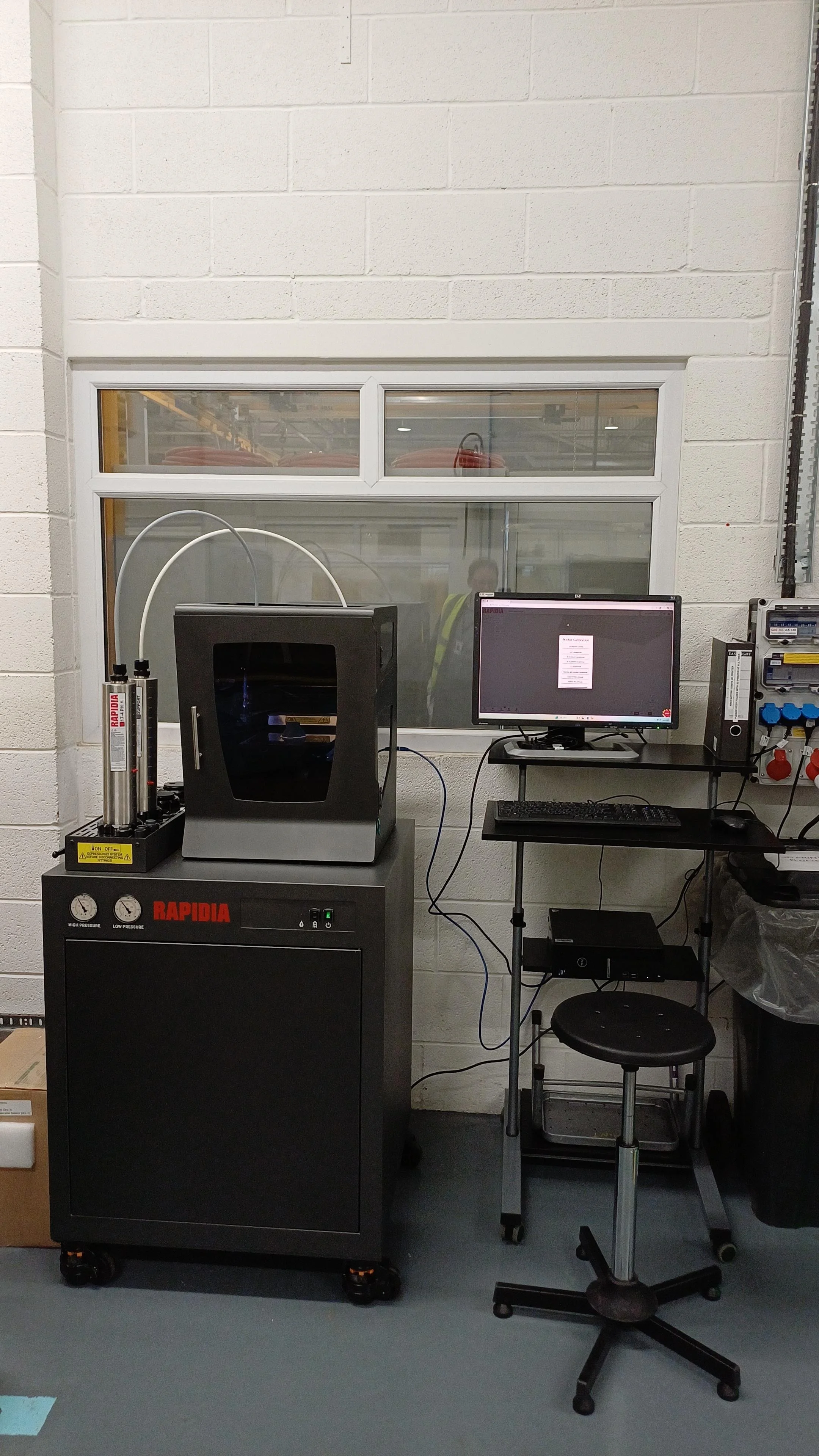
Rapidia Conflux 1 facility set upLeft) Conflux 1 furnaceRight) Conflux 1 PrinterWhat is MPD currently being used for?
The technology is already supporting Challenger 3, one of the UK’s most significant land capability programmes, through the manufacture of approved production components. At the time of writing, 7 small fabricated and / or machined part types have been approved for manufacture by MPD with more in the pipeline.
Even simple brackets can be more cost effective with MPD. For example, we’re currently experimenting with stacking parts to increase printer productivity and enhance cost effectiveness. This would make even the most basic of parts financially viable and challenge our assumptions of what is suitable for metal AM. For small parts and parts with complex geometries it is possible to see an 80% cost reduction vs. conventional manufacture in supply.
Beyond new build platforms, MPD in Rheinmetall UK is also being leveraged to support legacy platforms. Often tooling is no longer available and with spares being required in very low volumes, it is typical for parts to be uneconomical to produce and take many months to purchase from the traditional supply chain. An example of this is a Trojan deck hatch handle. Originally a cast component, replacing a single broken handle is an expensive prospect with very long lead times.
In this case, a spare was printed in 17-4PH stainless steel, a much higher performance steel than the original specification. The part could be printed in exactly the same geometry as the original part. Once painted, the part is visually indistinguishable from the original. This part will be the first metal AM part that Rheinmetall UK has incorporated into build standard and provides the British Army with a rapid procurement route for when these parts need replacing in the future. This work also demonstrates the art of the possible. Many other similar parts could be manufactured in this way, significantly reducing lead times and helping our customers maintain their fleet availability.
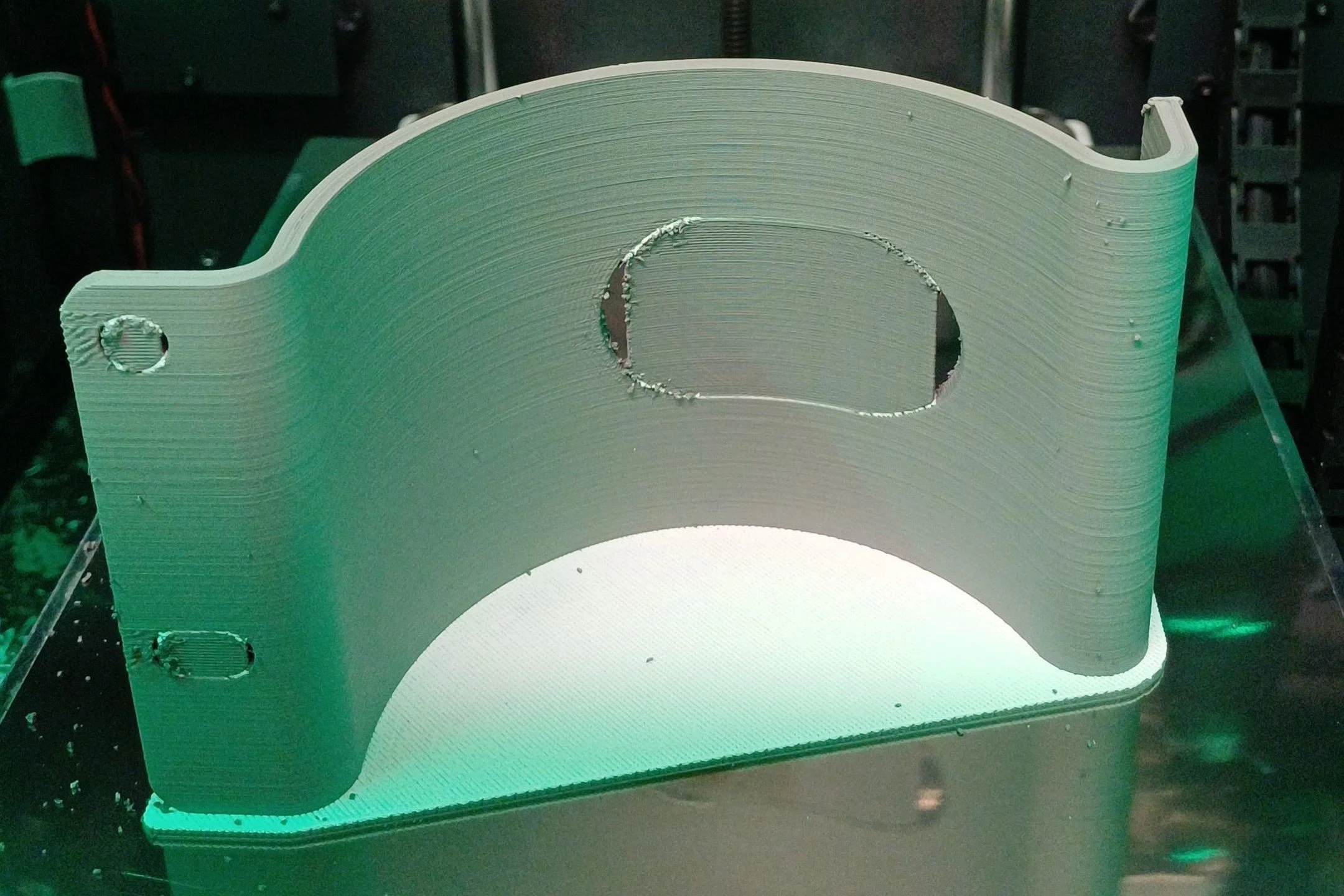
Simple geometries for additive manufacturing can be quite challenging for conventional manufacture e.g. rolled parts. The component illustrated was needed within a few days for a vehicle trial. Conventional supply chains couldn’t deliver the parts in time. With in-house MPD, it is possible to produce a part like this over the course of a day.
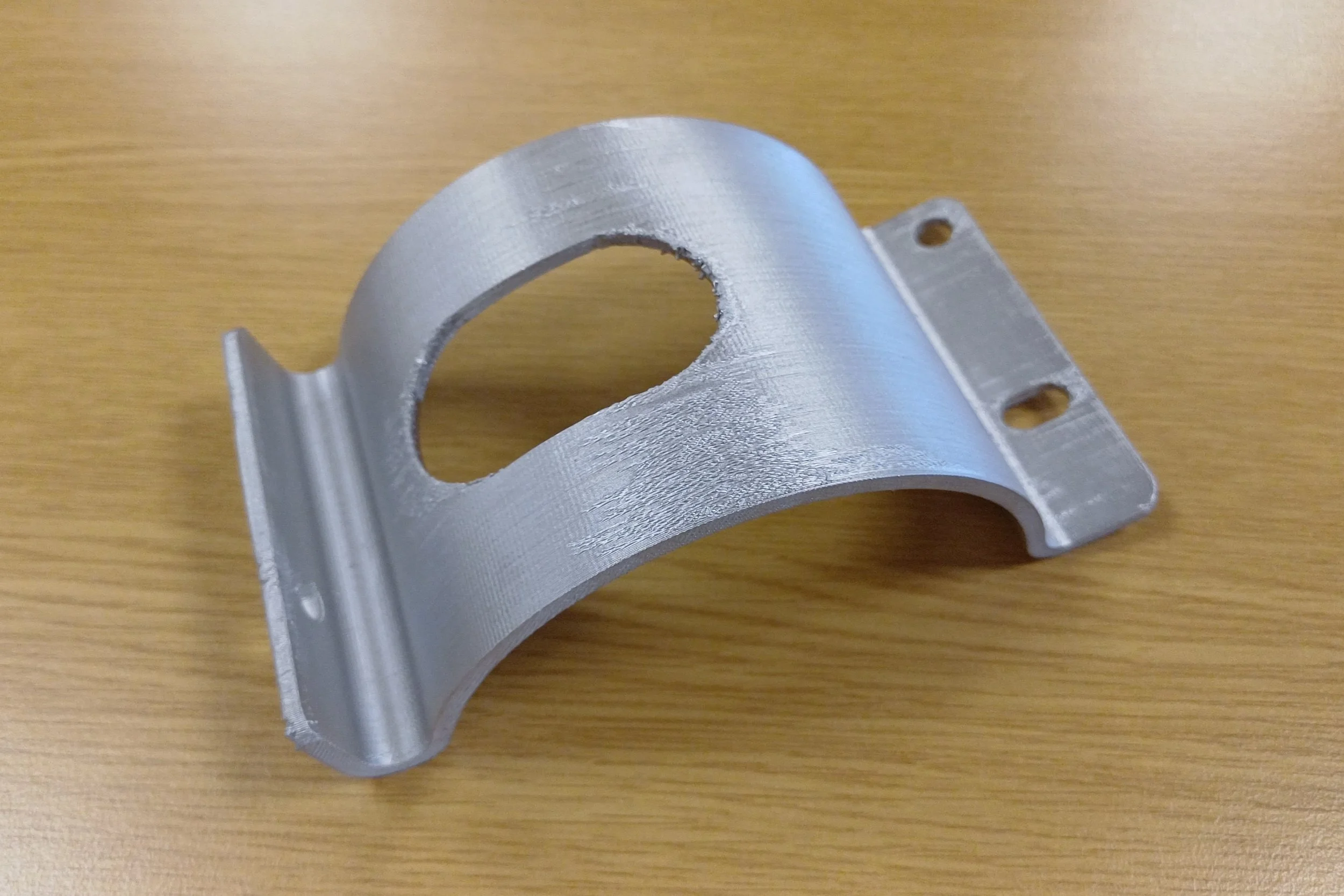
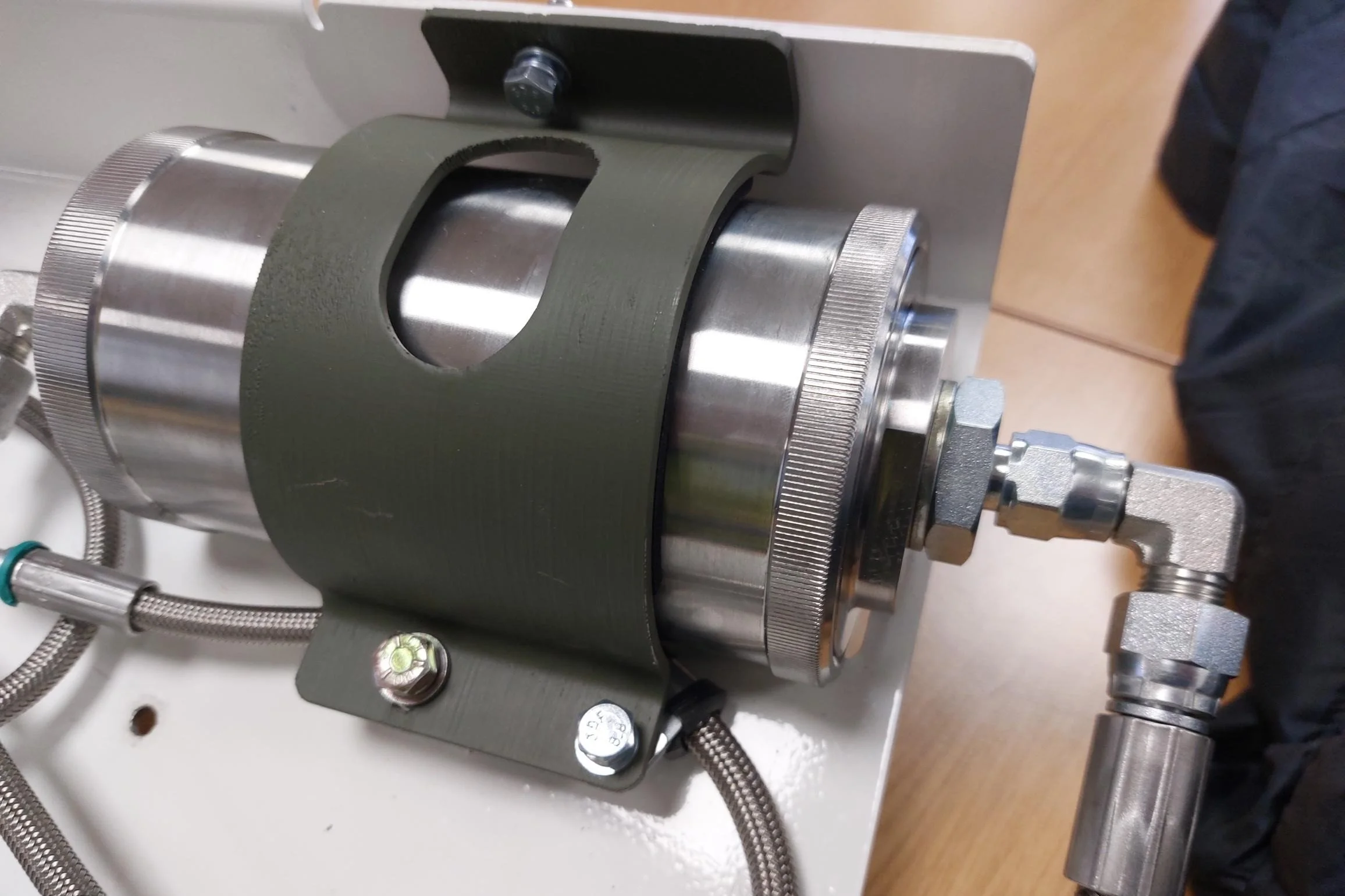
Through hybrid manufacturing methods, we have also been experimenting with manufacturing larger components than wouldn’t fit on the printer build bed or be possible to sinter in one piece. An example of this is a prototype design for a Land Rover brake pedal. This was printed in 4 separate parts and TIG welded with stainless steel wire. The prototype part is over 400mm long, took 24 hours to print all sections and needed a 12 hour sinter. The part is 40% lighter than the original and the materials cost £86. We took this approach to demonstrate that the part could be manufactured with minimal equipment i.e. just a Conflux 1 system and a welder. For better economics, it would make sense to laser cut the curved bar and only print the complex geometries. This would enhanced printer productivity and reduce part cost particularly if multiple parts were being made.
Bracket for the low pressure fuel system on a Bulldog armoured personnel carrier Left) as printed Centre) after sintering, no post processing used Right) painted and test fitting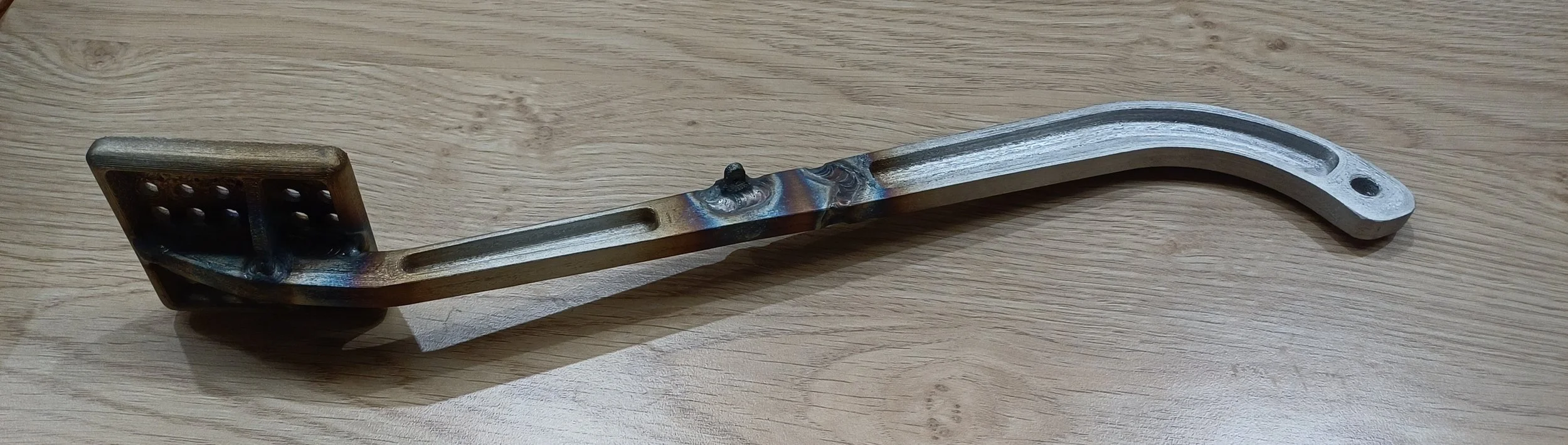
Prototype Land Rover brake pedal assembly manufactured with MPD in 4 sections and TIG welded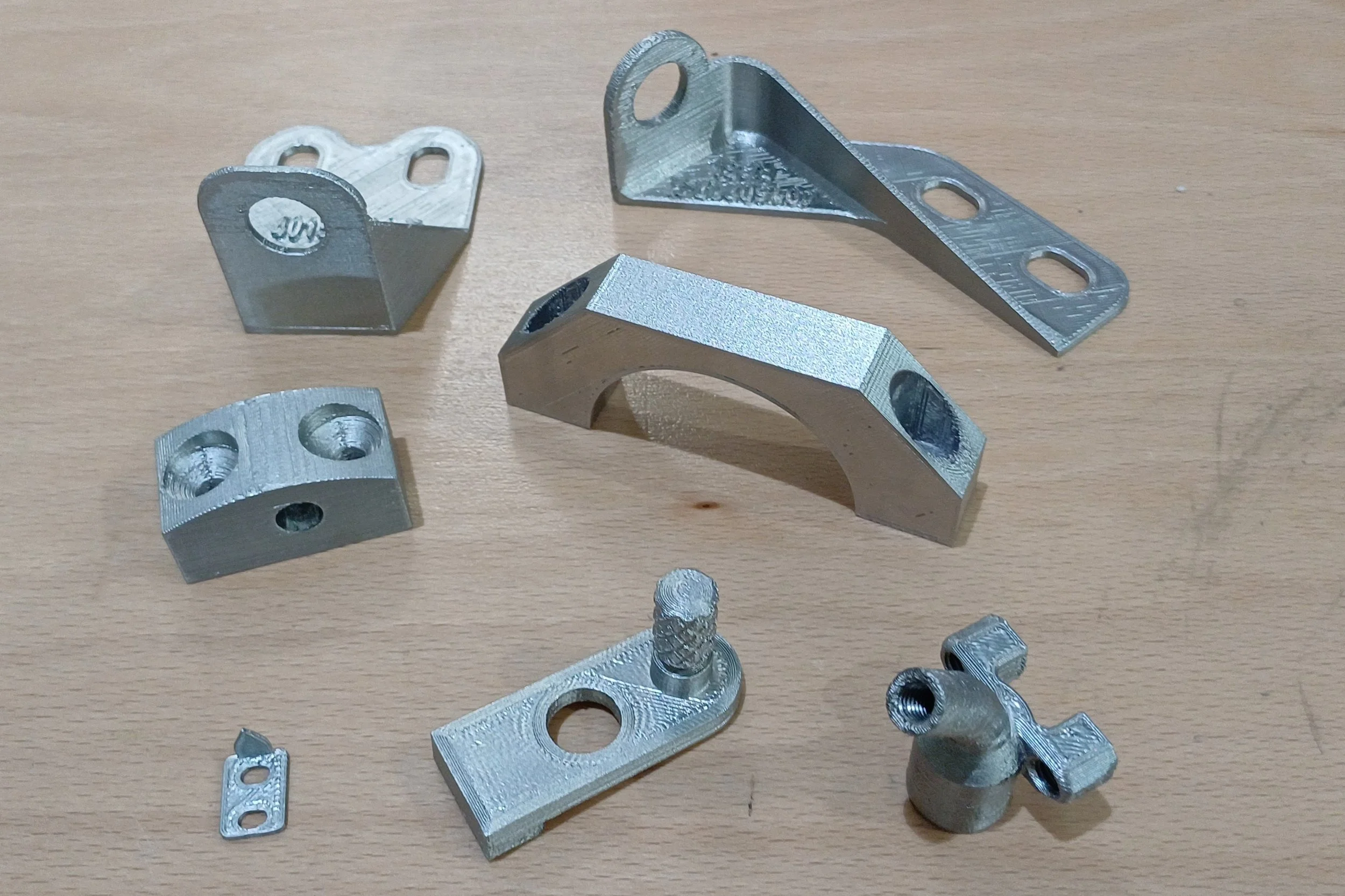
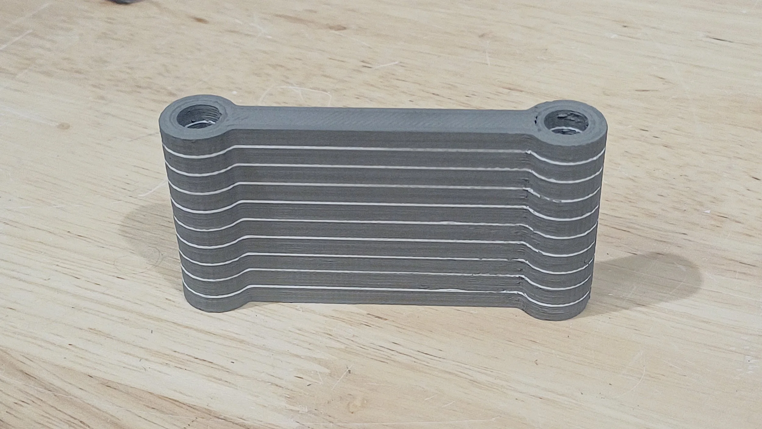
First seven MPD AM production prototypes approved for Challenger 3 build standardSimple tie strap stacked 10 parts high to optimise production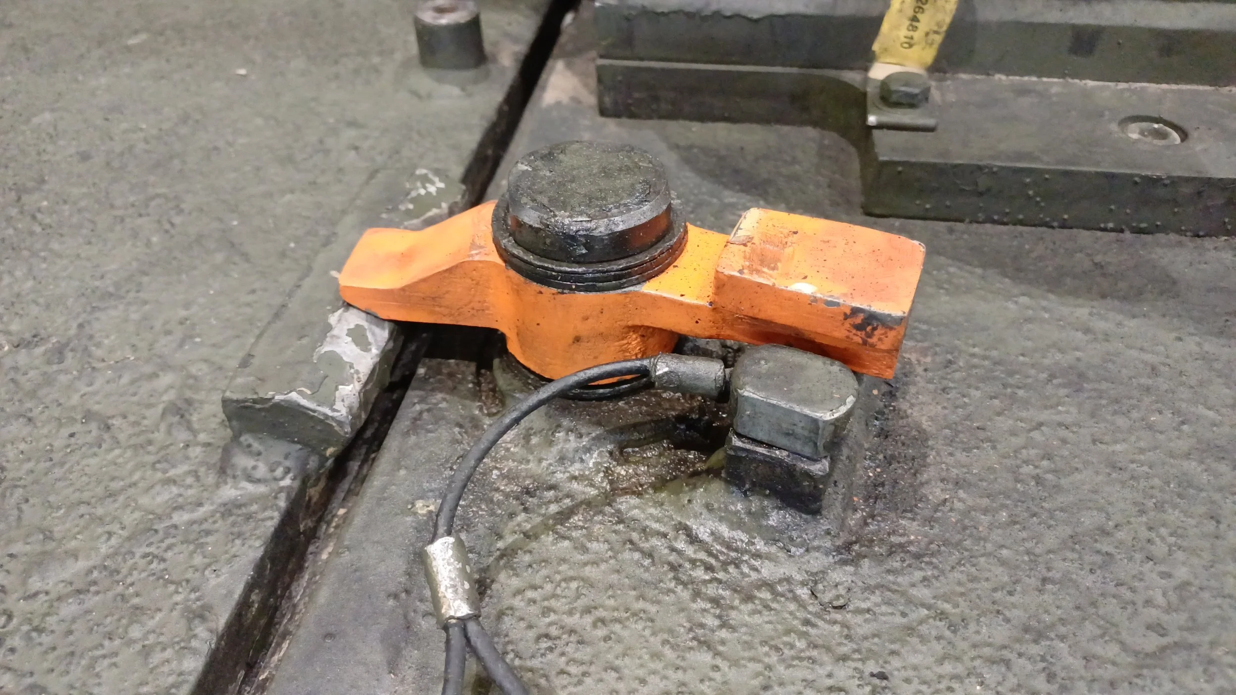
MPD AM Trojan deck hatch handle, painted orange for testing. 515g of steel final part weight, 135cc of metal paste used (including raft) requiring 16 hours of printing.What’s next?
From the first 7 months of use, we’ve seen how we can manufacture new build programme parts and spares for legacy vehicles faster and more affordably. We started by focusing on small, low critically components, however this doesn’t have to be the limit.
As we develop more experience with the technology, expand our datasets and prove our process qualification methods, higher criticality parts will come into scope. Additionally, hybrid manufacture techniques can open the door to larger parts that would otherwise be unsuitable for this process.
As more parts are being designed for this process, an exciting new opportunity is being presented. The printer and furnace are very power efficient, require minimal gas, occupy a small footprint, have minimal signature and are relatively robust to being moved. These characteristics lend themselves to a deployed manufacturing solution. Instead of manufacturing parts within the supply chain, our customer could take the equipment with them and manufacture parts at the point of need.
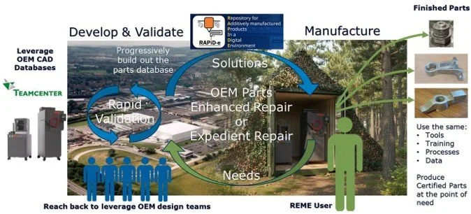
Vision for a deployed manufacturing capability that mirrors the process in Industry to enable OEM certified parts at the point of need.The building blocks of this capability have already been demonstrated so if feels very much within reach with current technology.
We are currently demonstrating how we can certify these parts for installation on military vehicles
We demonstrated exchanging AM part data over the NATO RAPiD-e system last year when the British Army were deployed on exercise in the USA
We have had British Army REME secondees working at our Telford facility using the equipment to manufacture parts
Earlier this year we showed that the equipment could be operated from an austere environment by supporting British Army’s deployment to AM Village hosted at Albacete airbase in Spain. The equipment was operated alongside Army’s mobile workshop, powered by a generator and working under a tarp. We were confident that this would work well as a company called IS4S and Rapidia had previously demonstrated a containerised Conflux 1 system for the US Navy.
With the capital cost of the equipment being much lower than other metal AM technologies, being lightweight and occupying a small footprint. It is conceivable that the equipment could be used to produce metal spare parts much closer to the point of need than is currently possible or even imagined. For repairs of military vehicles this could mean siting the production equipment a few hours drive from the front line rather than in a different country all together. Being low cost also means that it is more likely that users will be able to afford multiple instances of the equipment enabling capability dispersion and therefore increasing survivability on the battlefield. In today’s conflicts, centralised nodes become a high value target that have to be protected.
The future applications for this technology are exciting and could lead the way to radically change the way we support military capability.
In other services or industries, the ability to site the equipment where the parts are needed would be a game changer. For example, it could be sited on the dockside or even on ship, saving transporting spare parts around the world. For industries working in austere environments far from supply chains such as mining, it could reduce downtime for repairs.
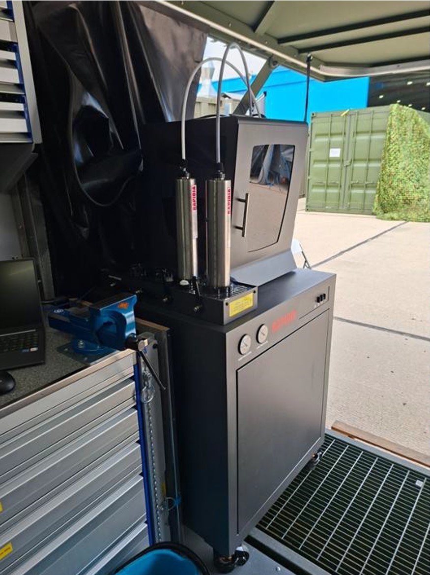
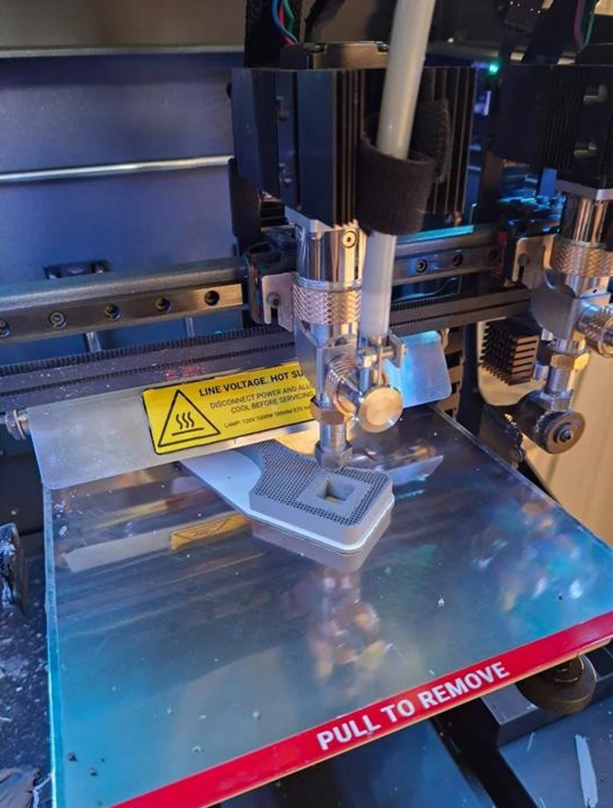
Conflux 1 metal paste deposition printer producing parts whilst deployed at AM Village, Albacete Air Base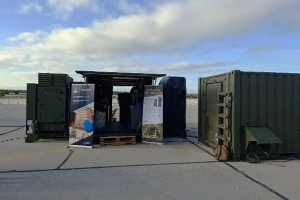
British Army’s deployment of their mobile workshop supported by Rheinmetall UK with our Rapidia Conflux 1